Faceplate example
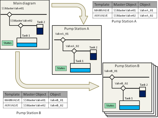
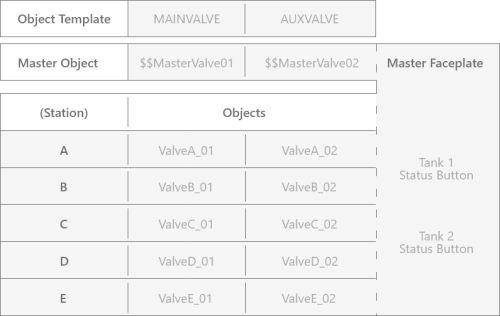
The illustration below provides an example of a faceplate set-up, using a master faceplate diagram and five faceplate instances (ref. the table further below).
In the example, the Main diagram is a master faceplate diagram and contains the master objects $$MasterValve01 and $$MasterValve02.
The $$MasterValve01 master object was created based on the MAINVALVE analog object template and the $$MasterValve02 master object was created based on the AUXVALVE analog object template.
The master faceplate also contains the status button for Tank 1 and Tank 2 objects which all are normal IGSS objects that are placed in the Master Faceplate. They are therefore accessible to all faceplates based on the Main diagram.

The master faceplate contains 5 faceplates: Pump Station A, B, C, D, and E (ref. table below), each with two objects defined and assigned to master objects.
All the faceplates are identical to the Main diagram.

Prerequisite
A prerequisite for working with faceplate masters and faceplates is too:
-
Create all necessary object templates.
-
Create objects based on the object templates to be used for the faceplates.
-
Finally, create master object ($$Objects) as placeholders to be used within the faceplate master.
It is recommended that digital, analog, counter and table objects used for master objects on a master faceplate diagram are based on an object template to be displayed in the underlying faceplate diagrams.
You can create and place an object that is not based on an object template on a master faceplate diagram, but the object will be visible on all the underlying faceplates and will not function as a master object. This goes for digital, analog, counter, string, scale, and table objects.
